- 您现在的位置:买卖IC网 > Sheet目录516 > SKY13268-344LF (Skyworks Solutions Inc)IC SW SPDT 300K-3GHZ SOT-666
DATA SHEET ? SKY13268-344LF
Pin Descriptions
Pin Number
1
2
3
4
5
6
Evaluation Board
Pin Name
J 2
GND
J 3
V 2
J 1
V 1
Description
RF input/output – RF input or output port which is either connected via a low insertion loss path to RF common (J 1 )
or isolated from RF common, according to the logic levels applied to V 1 and V 2
Equipotential point – Equipotential point for control voltage and RF circuits. Must be connected to PCB ground via
lowest possible impedance
RF input/output – RF input or output port which is either connected via a low insertion loss path to RF common (J 1 )
or isolated from RF common, according to the logic levels applied to V 1 and V 2
Control voltage – Control voltage input #2
RF common input/output – RF input/output port that is connected via low insertion loss path to either RF1 or RF2,
depending upon the voltage applied to control voltage pin
Control voltage – Control voltage input #1
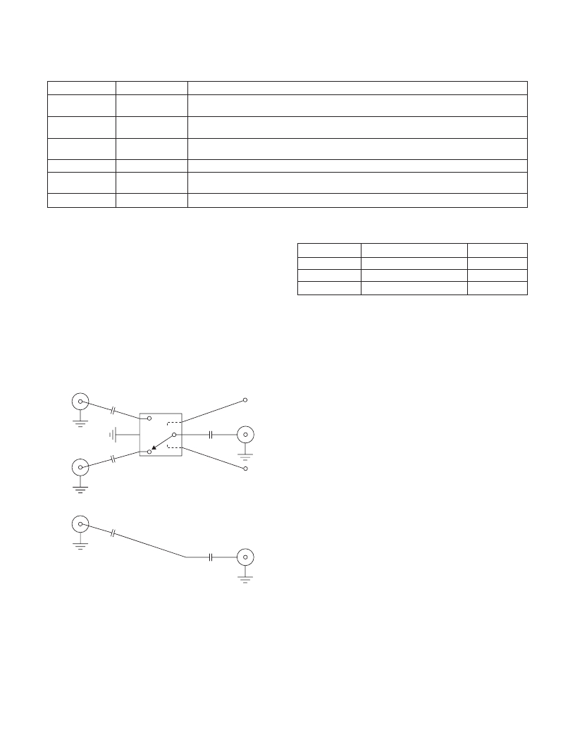
Evaluation Board Components
The evaluation board for SKY13268-344LF allows the part to
be fully exercised. The insertion loss of the transmission lines
between J 1 - U1 and U1 - J 2 /J 3 can be determined by measuring
the performance of the calibration through-line, which contains
two DC block capacitors in identical positions to the DC blocks
Component
C 1 –C 5
U1
J 1 , J 2 , J 3 , J 4 , J 5
Description
DC blocking capacitor
SKY13268-344 GaAs SPDT
SMA connectors
Default
100 pF, size 0402
present in the main circuit.
The state of the SKY13268-344LF is controlled by applying
the appropriate logic level voltages to ports V 1 and V 2 , per the
Truth Table.
SKY13268-344LF Evaluation Circuit
C 1
J 2
100 pF
C 3
100 pF
V 1
J 1
J 3
C 2
U1
V 2
100 pF
C 4
4
J 4
100 pF
C 5
100 pF
J 5
Calibration Through Line
Skyworks Solutions, Inc. ? Phone [781] 376-3000 ? Fax [781] 376-3100 ? sales@skyworksinc.com ? www.skyworksinc.com
June 19, 2009 ? Skyworks Proprietary Information ? Products and Product Information are Subject to Change Without Notice. ? 200037 Rev. H
发布紧急采购,3分钟左右您将得到回复。
相关PDF资料
SKY13272-340LF-EVB
IC SW 4X2 250MHZ-2.15GHZ 20-QFN
SKY13306-313LF
IC SWITCH SPDT 100M-6GHZ 6-QFN
SKY13316-12LF
IC SW SPST 300K-2.5GHZ 8-SOIC
SKY13321-360LF
IC SW SPDT 0.1-3.0GHZ GAAS 8QFN
SKY13335-381LF
IC SE SPDT 0.1-6.0GHZ GAAS 6MLPD
SKY13345-368LF-EVB
EVAL BOARD FOR SKY13345
SKY13347-360LF
RF SWITCH 3GHZ SPST
SKY13352-337LF-EVB
EVAL BOARD FOR SKY13352
相关代理商/技术参数
SKY13268-344LFB
制造商:Skyworks Solutions Inc 功能描述:RF AND MICROWAVE SWITCH
SKY13270-92LF
功能描述:RF 开关 IC .02-2.5GHz SPDT IL .4dB typ @ 1GHz RoHS:否 制造商:M/A-COM Technology Solutions 开关数量:Single 开关配置:SPDT 介入损耗:0.6 dB 截止隔离(典型值):43 dB 最大工作温度:+ 85 C 最小工作温度:- 40 C 安装风格:SMD/SMT 封装 / 箱体:PQFN-16 封装:Reel
SKY13270-92LF_EVB
制造商:Skyworks Solutions Inc 功能描述:Eval Board for SKY13270-92LF, Bulk
SKY13270-92LF-B
制造商:Skyworks Solutions Inc 功能描述:RF AND MICROWAVE SWITCH
SKY13270-92LF-EVB
功能描述:IC SW SPDT 100MHZ-2.5GHZ SC-70 RoHS:是 类别:RF/IF 和 RFID >> RF 评估和开发套件,板 系列:- 标准包装:1 系列:- 类型:GPS 接收器 频率:1575MHz 适用于相关产品:- 已供物品:模块 其它名称:SER3796
SKY13272-340LF
功能描述:RF 开关 IC .25-2.15GHz 4 X 2 Switch -40C +85C RoHS:否 制造商:M/A-COM Technology Solutions 开关数量:Single 开关配置:SPDT 介入损耗:0.6 dB 截止隔离(典型值):43 dB 最大工作温度:+ 85 C 最小工作温度:- 40 C 安装风格:SMD/SMT 封装 / 箱体:PQFN-16 封装:Reel
SKY13272-340LF_EVB
制造商:Skyworks Solutions Inc 功能描述:Eval Board for SKY13272-340LF, Bulk
SKY13272-340LFB
制造商:Skyworks Solutions Inc 功能描述:RF AND MICROWAVE SWITCH
